ASIC laboratory Heidelberg
 |
Content
Schematics entry with the Composer schematics editor
Composer is the schematics editor that comes along with Cadence and which is used for schematics entry for ASIC design. This is a powerful tool and it is strongly recommended to read the Composer documentation. Most easily you reach the Online documentation by clicking the Help button at the top right corner of the Composer window shown below.

Drawing an inverter
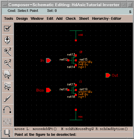
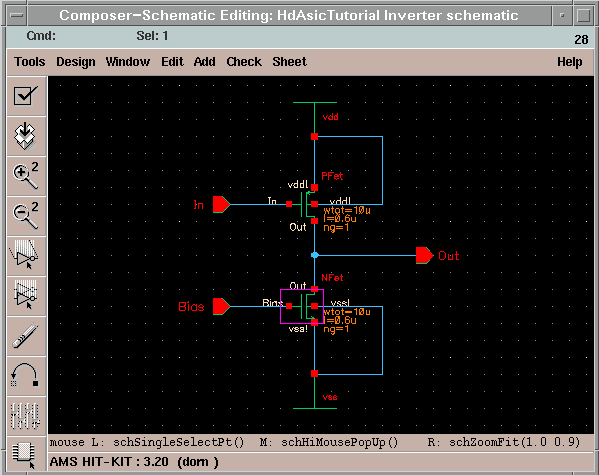
To exercise drawing with Composer we want to draw an inverter. Go to Add -> Instance... and click the browse button to select the PRIMLIB library. Choose in Cell the nmos4 and as view symbol. Now you can place the symbol in the drawing area of the Composer. Repeat this procedure for the pmos4. For the powersupply we need the analogLib library. Because of the volume of this library it is better to check the Show Categories button. In the category Sources you find the subcategory Global. Place the vdd and the vss on the schematic sheet. With the keyboard key ESC you can leave the Add -> Instance... dialog.


